-
Glass Fused To Steel Tanks (896)
-
Stainless Steel Tanks (434)
-
Fusion Bonded Epoxy Tanks (652)
-
Galvanized Steel Tanks (321)
-
Aluminum Dome Roofs (1336)
-
Wastewater Storage Tanks (280)
-
Welded Steel Tanks (457)
-
Pressure Vessels (396)
-
Anaerobic Digester (202)
-
Industrial Water Tanks (349)
-
Glass Lined Steel Tanks (180)
-
Bolted Steel Tanks (389)
-
Sludge Storage Tank (115)
-
Biogas Storage Tank (173)
-
Leachate Storage Tanks (133)
-
Agricultural Water Storage Tanks (179)
-
Fire Water Tank (166)
-
Grain Storage Silos (146)
-
Biogas Projects (424)
-
Wastewater Treatment Projects (1702)
-
Double Membrane Roof (223)
|
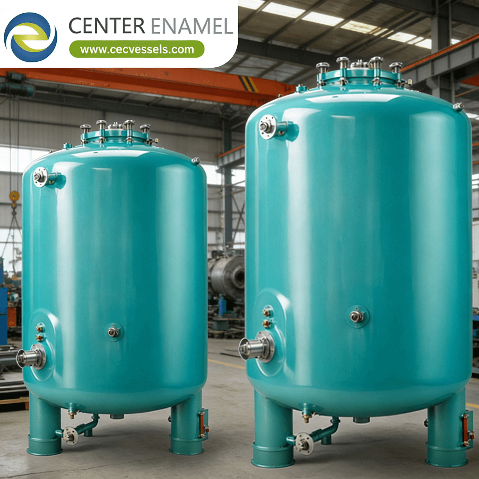
What Is a Pressure Control Reactor? Principles, Technologies & Applications
| Place of Origin: | China |
| Brand Name: | Center Enamel |
| Certification: | ISO 9001,CE, NSF/ANSI 61, WRAS, ISO 28765, LFGB, BSCI, ISO 45001 |
| Minimum Order Quantity: | 1 Sets |
| Price: | 2000 |
| Delivery Time: | 2 months |
| Payment Terms: | L/C,T/T |
| Supply Ability: | 200 sets / days |
|
Detail Information |
|||
Product Description
What Is a Pressure Control Reactor? Principles, Technologies & Applications
Answering the core question: What is a pressure control reactor, and how does it maintain precise pressure regulation in high-pressure chemical processes? A pressure control reactor is a chemical reactor equipped with active pressure regulation systems that maintain operating pressure within +/-0.01 to +/-0.1 MPa of setpoint across operating ranges from vacuum (-0.1 MPa) to 50 MPa (supercritical water oxidation). Key components include a back pressure regulator (BPR) on the vapor/liquid outlet, a PID (Proportional-Integral-Derivative) control loop with pressure transmitter feedback (response time 0.1-5 seconds), a nitrogen or inert gas pad for overhead pressure maintenance, and pressure relief devices per ASME UG-125 (PSV set at MAWP, with accumulation limited to 110% MAWP for single relief valve). These reactors are essential for hydrogenation (2-15 MPa), polymerization (1-30 MPa), supercritical CO2 extraction (7-48 MPa), and hydrothermal synthesis (10-40 MPa) where pressure directly affects reaction kinetics, phase behavior, and product selectivity.
1. Core Pressure Control Principles and Technologies
Pressure control reactor systems rely on three engineering principles:
- Back Pressure Regulation and Flow Modulation The back pressure regulator (BPR) is a spring-loaded or dome-loaded valve installed on the reactor outlet that maintains upstream pressure by modulating the outflow. Dome-loaded BPRs (Air-Loaded or I/P-controlled) use a pilot pressure signal (0.02-0.1 MPa air or nitrogen) to set the control pressure remotely, enabling automated adjustment. BPR sizing requires Cv (flow coefficient) calculation per ISA-75.01: Cv = Q x sqrt(SG / delta-P), where Q is flow, SG is specific gravity, and delta-P is the pressure drop across the valve. A 100 L hydrogenation reactor with 5 MPa operating pressure and 10 L/min vent gas flow requires Cv = 10 x sqrt(0.09/4.9) = 1.35.
- PID Control Loop and Pressure Transmitter Feedback The pressure control loop consists of a pressure transmitter (Rosemount 3051S, accuracy +/-0.04% of span, response time 100 ms), a PID controller (DCS or standalone, scan rate 0.1-1 second), and a final control element (BPR or control valve). PID tuning uses Ziegler-Nichols or Cohen-Coon methods: for a 5 MPa hydrogenation reactor, typical tuning parameters are Kp = 2-5, Ti = 10-30 seconds, Td = 2-5 seconds. Cascade control (outer loop pressure, inner loop flow) improves response for rapid pressure disturbances from gas consumption or generation.
- Overpressure Protection and ASME UG-125 Compliance ASME Section VIII Division 1 UG-125 requires every pressure vessel to have a pressure relief device (PRV or burst disc) with set pressure not exceeding the maximum allowable working pressure (MAWP). For single-valve protection, accumulation is limited to 110% MAWP; for multiple valves, 116% MAWP. Burst discs (reverse-acting or forward-acting) provide fail-open protection with response time <5 milliseconds, while spring-loaded PSVs respond in 50-200 milliseconds. A common configuration uses a burst disc upstream of a PSV (3% tolerance rule per ASME UG-135 for inlet piping losses) to isolate the PSV from process fouling while providing redundancy.
2. Major Pressure Control Configurations
Industrial pressure control reactor configurations are selected by pressure range, phase state, and control precision requirements:
- Gas-Phase Overhead Pressure Control with Inert Pad A nitrogen or argon blanket maintains a constant overhead pressure in the reactor vapor space using a pressure-reducing regulator on the inlet (set at the desired pad pressure, e.g., 0.3 MPa) and a back pressure regulator on the vent (set 0.05-0.1 MPa above pad pressure). This configuration is standard for oxidation-sensitive reactions, flammable solvent processing, and reactions generating non-condensable gases. Control precision is +/-0.02 MPa with a 50-100 L vapor volume.
- Liquid-Phase Back Pressure Control for Supercritical Systems For supercritical CO2 extraction (7-48 MPa) and supercritical water oxidation (22-40 MPa), a liquid-phase BPR on the reactor outlet maintains pressure with precision of +/-0.1 MPa. The BPR must handle temperature to 200C (CO2) or 600C (SCWO) and flow of 5-200 kg/h. Multi-stage pressure reduction (first BPR to 5 MPa, second to 0.1 MPa) prevents cavitation and flash boiling. A Coriolis mass flow meter on the outlet provides density-based phase verification.
- Differential Pressure Control for Continuous Flow Reactors In continuous flow systems, the pressure is maintained by a BPR on the outlet while a feed pump (HPLC or metering) controls inlet flow. The differential pressure (delta-P = P_in - P_out) drives flow through fixed catalyst beds or microreactor channels. For a packed-bed flow reactor at 10 MPa with 50 mL/min flow through 200 g catalyst (bed length 100 mm, void fraction 0.4), the Ergun equation predicts delta-P = 150 x mu x v x (1-eps)^2 / (eps^3 x D_p^2) + 1.75 x rho x v^2 x (1-eps) / (eps^3 x D_p), requiring a BPR that handles 10 MPa and flow to 200 mL/min.
Pressure Control Configuration Comparison Matrix
Configuration |
Pressure Range & Precision |
Control Method |
Typical Application |
Gas-Phase Inert Pad |
0.1-1.0 MPa, +/-0.02 MPa precision |
Inlet reducing regulator + outlet BPR, PID |
Oxidation-sensitive reactions, flammable solvents, gas-generating reactions |
Liquid-Phase BPR |
7-48 MPa, +/-0.1 MPa precision |
Dome-loaded BPR, multi-stage reduction, Coriolis feedback |
Supercritical CO2 extraction, SCWO, hydrothermal synthesis |
Differential Pressure (Flow) |
0.5-50 MPa, +/-0.05 MPa precision |
Feed pump + outlet BPR, Ergun equation delta-P sizing |
Continuous flow catalysis, packed-bed reactors, microreactor systems |
Frequently Asked Questions (FAQ)
Q: What is the ASME UG-125 requirement for pressure relief on a pressure control reactor?
A: ASME Section VIII Division 1, paragraph UG-125 requires that every pressure vessel be protected by a pressure relief device (spring-loaded PSV or burst disc) with set pressure not exceeding the maximum allowable working pressure (MAWP). For a single relief device, the accumulation (maximum pressure during relief) must not exceed 110% of MAWP. For multiple devices (PSV + burst disc in parallel), accumulation is limited to 116% of MAWP. The 3% rule (UG-135) limits inlet piping pressure drop to 3% of set pressure to ensure proper PSV operation.
Q: How is a back pressure regulator (BPR) sized for a chemical reactor?
A: BPR sizing uses the ISA-75.01 flow coefficient equation: Cv = Q x sqrt(SG / delta-P), where Q is the maximum flow rate (gpm for liquid, scfm for gas), SG is specific gravity, and delta-P is the pressure drop across the valve. For a 100 L hydrogenation reactor at 5 MPa with 10 L/min nitrogen vent flow: Cv = 10 x sqrt(0.96 / 49) = 1.40. The selected BPR should have a rated Cv of 1.5-2.0x the calculated value for margin, and materials must be compatible with process media and temperature.
Q: What PID tuning parameters are typical for reactor pressure control?
A: For a medium-volume batch reactor (100-2000 L) with gas-phase pressure control, typical Ziegler-Nichols PID tuning parameters are: Proportional gain Kp = 2-5, Integral time Ti = 10-30 seconds, Derivative time Td = 2-5 seconds, with a controller scan rate of 0.1-1 second. The process time constant (pressure vessel volume divided by vent rate) typically ranges from 10-100 seconds. For faster-responding microreactors (<1 mL), scan rates of 10-50 milliseconds and Kp = 0.5-2 are used. Cascade control (outer pressure loop, inner flow loop) improves disturbance rejection for reactions with rapid gas consumption or generation.
Q: Why is a burst disc installed upstream of a PSV in some pressure control reactors?
A: A burst disc upstream of a PSV provides three benefits: (1) isolation of the PSV from process fouling, corrosion, or polymer buildup that could prevent the PSV from opening at set pressure; (2) fail-open redundancy, as the burst disc opens in <5 milliseconds versus 50-200 ms for a PSV; (3) a telltale pressure gauge between the burst disc and PSV detects disc rupture, prompting replacement. The 3% rule (ASME UG-135) applies to the combined inlet piping plus burst disc pressure drop, requiring careful hydraulic analysis to ensure the PSV still functions correctly when the burst disc opens.